There is not a type of farm equipment that has not been exposed to the integration of electronics. Long gone are the days of the hand crank starter with magneto and wondering if the seed is going into the ground.
Today we have electronic diesel engines, advanced planters with precision controls and sensors, along with combine cabs with enough monitors that to the untrained eye one would think it is the space shuttle!
All of this has helped to increase crop yields and make farming more profitable — that is when they work. Technology is a wonderful thing but it is a double-sided sword — a real headache when things go wrong.
When trying to figure out why an electrical device is not functioning most of us apply the logical step of grabbing the voltmeter and checking the power supply.
The conventional wisdom being if it has power it should work. If not, the problem must be in the component — a faulted logic that often leads us astray. But confirming the input voltage is only half of the equation — a D.C. circuit needs a proper ground to function correctly.
Power and ground
When confronted with an electrical device that is either not working or showing misbehaviour, the proper protocol is to confirm the input voltage with an accurate meter.
Every device has what is defined as a threshold voltage – the minimum voltage required to function. The electrical system in most if not all equipment is designed to operate on 12-volts but the alternator will put out between 14 to 15 volts.
The circuit needs to be confirmed for a low or high voltage condition — either will cause an issue. If the voltage is correct then your attention needs to be focused on the ground-side of the circuit.
A circuit can have the voltage supply or the ground switched on and off. A headlight traditionally has the voltage switched and a fixed ground. Most windshield wiper motors have a constant voltage supply and the ground path is controlled.
The proper mindset when working with electronics is to accept that in most instances there is no predictor of how the circuit will respond with a poor ground. A light is different. It will be dim.
In contrast, a sensor or control panel on a combine or tractor may do some very strange things when faced with a poor ground. Do not jump to conclusions — assign values. This is especially true when it comes to sensors on farm equipment since most work on low voltage and cannot tolerate even a marginal ground circuit without skewing.
Poor ground circuits are not limited to advanced agricultural electronics only. The procedures in this primer can be applied to any equipment on the farm. The protocol will be just as effective on an antique tractor, grain truck, farmstead mower or any other piece of equipment that you want to check a ground circuit on.
How to check a ground
Many of you may already be checking ground circuits and using an ohmmeter to do so. That may be the way you were taught; but it would be akin to taking only one soil sample from a 100- acre field and saying it represents the entire area. Let me explain.
An ohmmeter has no polarity and uses an internal battery to send a minute voltage into the circuit or component being tested. By definition ohms is a reading of opposition to current flow.
It should only be employed to confirm continuity or the specification of a part such as a sensor or motor winding. Zero means no opposition to flow and infinity represents an open circuit. Anything in between can be thought of as an electrical version of frictional flow loss through a pipe.
The problem with checking a ground circuit with an ohmmeter is that it does not represent the ability to carry an electrical load. A ground can check out with zero resistance and still be poor.
You can prove this to yourself with a small piece of stranded battery cable from your farm shop. Pull back the insulation and separate one of the wire strands. Connect the ohmmeter set on the lowest scale to the single strand and to the complete wire on the other end. It will show continuity.
Now take the single strand and reconnect it with the others and retest. The ohmmeter reading will be almost the same if not the same. But you know that if it were a circuit with a high electrical load such as the starter motor, the engine would never crank thru one strand of copper wire. For this reason, using an ohm test to confirm a ground circuit is faulted. The only accurate method to check a ground is with a voltage drop test.
If anyone has ever diagnosed an electric fence controller with a fence tester then you unknowingly performed a voltage drop test. Most fence controller makers will state that there should be no more than 300 volts on the ground rod and preferably a lot less.
The easiest way to think of a voltage drop test is to liken it to an on ramp for a highway. If the traffic flow is smooth and not too busy then there are no cars backed up waiting to merge. If the opposite is true, then there is a traffic jam.
The voltage drop test measure the traffic jam of electrons waiting to get to ground. If the ground path is good then there are few if any electrons waiting there. But if the ground has high resistance, then there is a large traffic jam.
Instead of counting cars waiting to merge on the highway we are looking at volts. This test identifies the true effectiveness of the ground circuit while an ohm reading will not provide that picture. If the circuit is completely open then the ohmmeter will show that by reading infinity but that is rarely the case. Most ground related electrical problems on farm equipment are traced to a poor ground and not an open one.
It is very easy to perform a voltage drop test on a ground circuit. The only issue being that depending on the piece of equipment you may need to make up a very long lead with alligator clips on the end to reach the negative battery cable. Keep a spool of inexpensive automotive-type wire in the shop and you will be able to check anything on the farm.
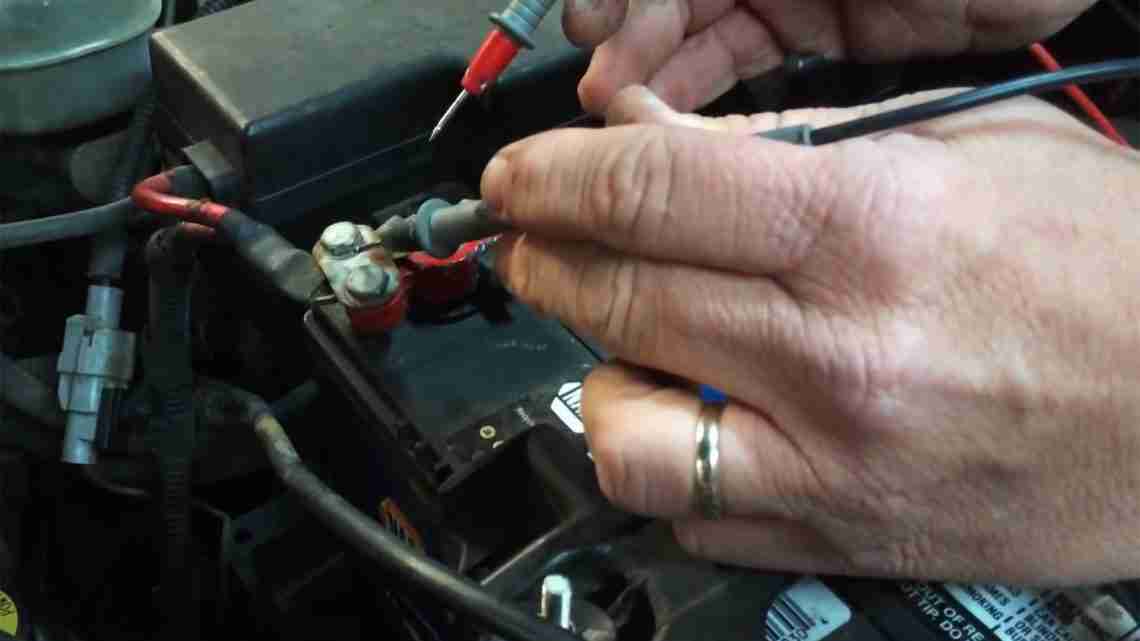
The test procedure is very simple. The circuit that is being tested must be powered-up and activated, so you may require a helper.
Place the meter’s negative lead on the battery negative cable and the positive lead on the ground being test. Activate the circuit and read the meter. A good ground will have a maximum of 3/10th (0.30) of a volt on the circuit.
Anything more than that and the ground is poor. To check the battery ground, connect the negative lead of the meter to the negative post of the battery and the positive lead to the engine block ground and have a helper crank over the engine. The same specification will hold true.
When dealing with advanced agricultural electronics such as seed flow meter, etc, ask the manufacturer for the ground drop specification they require. With a low voltage circuit, a reading over 1/10 of a volt may be a problem.
Repairing a ground
Most ground problems on farm machinery are rooted in a rusty and corroded connection where the wire attaches to metal. Another problem is paint under the connection; a real issue with restored tractors that are made to look pretty. Other concerns are corrosion in the connector from the wire and broken strands.
When replacing a connector even a crimp style design, it should always be backed up with solder and either a shrink-wrap or good quality electrical tape. Corrosion that migrates between the wire and the connector will add resistance to the ground circuit.
All paint should be removed under the ground lug area and the connector treated with dielectric grease. If the equipment dealer does not offer this product a good auto parts store will.
Confirming ground circuit integrity before you enter the field is quick and easy. It will help prevent problems once you get going and should become part of your PM program. Most grounds go bad over time unless the wire suffers a break. Thus, a circuit that worked one day may not function the next since the resistance increased to a critical level.
You would never fertilize without first taking a soil sample so why go in the field without confirming the equipment’s ground circuits? Just think of it as a soil test for electric.